PWM devices for the MSX
The MSX standard has native support for the PWM protocol. This document describes how to create some devices and adapters that use it, and how to read such devices.
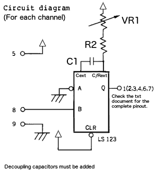
This is the basic circuit of one PWM channel, and will be used as a
building block for all devices for the MSX listed on this page:
The variations on each circuit will be:
- The amount of PWM channels used
- The value for each component
- The pinout to connect to the MSX joystick port
Please note that each 74LS123 chip features two PWM channels. When only
one of its channels is used, the other must be disabled to avoid
interference.
The 74HCT123 is a more modern replacement and should be preferred
instead of the 74LS123. The components in this page were calculated for
the two chips when possible.
Hardware
1) MSX-Paddle:
It uses a single PWM channel, and can have up to five digital buttons.
It's recommended to assemble them with at least three buttons: A, B and
START.
a) Components
b) DE9 female connector pinout
type-1: Up to 5 buttons (tip: designed to use NES or SMS joypad cases. Just add the extra buttons)
1: aX (Q-pin of the 74HCT123)
2: START button
3: Shoulder L1
4: Shoulder R1 / diode to NOT(pin-8)
5: Vcc
6: A button
7: B button
8: B-pin of the 74HCT123 and common pin for all digital buttons.
9: GND
type-2: Up to 8 buttons (tip: designed to use SNES joypad cases)
1: aX (Q-pin of the 74HCT123)
2: START button / SELECT button
3: Shoulder L1 / GND
4: Shoulder R1 / 10K pull-up to Vcc
5: Vcc
6: A button / X button
7: B button / Y button
8: B-pin of the 74HCT123, pin-1 of the 74HCT157 that selects each pair of buttons.
9: GND
Be sure to connect the inputs of the second channel as described below,
to disable it and prefent it from producing spurious oscillations:
- A2: GND
- B2: Vcc
- CLR2: Vcc
- C/Rext2: 10K resistor to Vcc
- Cext2: 10K resistor to GND
2) IBM-PC DA15 joystick adapter (AKA joyDA15 adapter)
This adapter uses two monostable channels.
a) Components for each channel
- For 74HCT123
- C1=68nF
- VR1=100K (already present inside the joystick)
- R2=330R
- For 74LS123
- C1=47nF
- VR1=100K (already present inside the joystick)
- R2=330R
b) DE9 female connector pinout and connections
1: 74HCT123 pin13
2: DA15 pin10
3: 74HCT123 pin5
4: DA15 pin14
5: DA15 pins 1,8,9 and 74HCT123 pin16
6: DA15 pin2
7: DA15 pin7
8: 74HCT123 pins 2 and 10
9: DA15 pins 4,5, and 12
- resistor R2_Y: pin1=74HCT123 pin7, pin2=DA15 pin6
- resistor R2_X: pin1=74HCT123 pin15, pin2=DA15 pin3
3) Atari-2600 dual-paddle adapter
a) Components
- 74HCT123 only
- C1=6.8nF
- VR1=1M (already present inside the paddle)
- R2=3K3
b) DE9 female connector pinout
1: 74HCT123 pin5
2: N/C
3: N/C
4: 74HCT123 pin13
5: 74HCT123 pin16 and Paddle DB9_pin7
6: Paddle DB9_pin3
7: Paddle DB9_pin4
8: 74HCT123 pins 2 and 10, and Paddle DB9_pin8
9: GND
- resistor R2_A: pin1=74HCT123 pin15, pin2=Paddle DB9_pin9
- resistor R2_B: pin1=74HCT123 pin7, pin2=Paddle DB9_pin5
Software Programming
- Analog channels are addressed by their ID, where ID=CH*2+JP.
- CH=Channel index (0 to 5), and JP=Joystick port (1 or 2).
- The pinouts and channels were arranged to ensure cross
compatibility between the PWM devices, and easier integration with
non-PWM devices on joylib.
1) Channel mapping
The channels will be mapped as follows. See the Assembly and MSX-BASIC sections on how to read each channel.
a) MSX-Paddle
Channel
0 : aX (analog X)
1 : START button / SELECT button
2
: L1 shoulder button / (optional) L2 shoulder button
3
: R1 shoulder button / (optional) R2 shoulder button
4 : A button / X button
5 : B button / Y button
buttons SELECT, L2, R2, X and Y are read by setting the pin-8 of the joyport to high.
b) joyDA15 adapter
Channel
0 : aX (analog X)
1 : X button
2 : aY (analog Y)
3 : Y button
4 : A button
5 : B button
c) Atari-2600 dual-Paddle
Channel
0 : Paddle-1 analog X1
3 : Paddle-2 analog X2
4 : Paddle-1 button
5 : Paddle-2 button
d) Generic template for a dual-analog joystick
Channel
0 : aX1 (analog X1)
1 : aX2 (analog X2)
2 : aY1 (analog Y1)
3 : aY2 (analog Y2)
4 : B button / A button
5 : C button / START button
The digital buttons will have the
following output: 00=Pressed, FFh=released. A and START buttons are
read by setting the joyport pin-8 to high.
e) Yamaha MMP-01
Check this article for the channel assignment on this device.
2) MSX-BASIC programming
- The Buttons A and B can be read normally with STRIG(N), or also via their respective analog channels as described below.
- All channels can be read using the PDL(ID) function. Analog
channels will return a value between 0 and 255, while digital buttons
will return either 0 (pressed) or 255 (released).
- The MSX-BASIC is too limited to be able to reliably identify the
connected device. When needed, it's better for BASIC programs to have
an option to allow the user to manually select the desired device.
3) Assembly programming
- The analog channels can be read with the GTPDL BIOS function and the same IDs used in MSX-BASIC.
- It's better to obtain the Digital buttons status by reading the PSG R#14 with RDPSG. The bits will be mapped like this:
- Paddle : ?,?,B,A,START,?,TL,TR
- joyDA15 : ?,?,B,A,C,?,D,?
The bits marked with "?" may contain random values and must be masked out from readings.
Be careful to handle devices that are different than the
standard MSX 2-button joystick, to avoid the infamous bug that some
games have, where when a different device is left connected to the
joystick port, the game has undesired collateral effects like
interpreting a stuck direction.
The connected devices can be identifyed in assembler by their fingerprints. The best way is to use HIDlib, as it handles both the
detection and the disconnection of all MSX-HID devices.
4) MSX turboR support
Originally, the MSX turboR models had the drivers for PWM devices and
Light-pen removed from their BIOS. But now you can use them back. All
you have to do is to install the TRnewdrv drivers available at this page.
5) Notes
These are hobbyist projects. Build and use them at your own risk.