MSX hardware fixes and enhancements
How to fix some flaws in many MSX
models
The MSX are great machines. But still, some of them had some design
mistakes here and there. This page shows quick DIY guides so you can
fix/improve your favorite model.
Disclaimer: There's no guarantee and I
won't be responsible for any damage to your equipment. Do any of
the fixes published here by your own choice and at your own
risk.
General tips:
- Do not try to salvage the old components, as they're cheap and
easy to find. That would unnecessarily increase the risk of
damage to the PCB. Just cut their pins, heat the solder that
holds them and gently remove the pins using a plier.
- When working on the PCB, be very careful to not apply torsion
on it as it might cause cracks in the soldering of the SMD
chips. A lot of MSX motherboards are made of phenolic paper and
this material bends somewhat easily.
1) Explanation of the most common design mistakes fixed here
1.1) Sound Fixes:
There were two common mistakes in the sound circuitry of MSX
computers:
- The standard specifies that all the sound input must be done
at -5dBm, so obviously all internal devices must be calibrated
at this level
- Yamaha seem to have made a mistake in the low-pass filter
shown in page 21 of the YM2413 datasheet. It's a decimal point
error. The capacitor was shown with a 0.015uF value, when it
should have 0.0015uF (IOW, 1.5nF). Because of that, the 1st
filter ended up having a 2.257KHz cut-off frequency, way lower
than the 20KHz recomended by the page 20 of the very same
document. This resulted in a muffled/dull sound.
Once the machine is fixed, test it with your favorite SCC+PSG and
specially the FM+PSG songs (i.e.: Microcabin). All the accords will
match perfectly, the sound will now be sharp and rich, and the bass
frequencies will be full.
1.2) Jailbars
Jail bars are a common type o artifact that appears on video of many
machines designed in the 80s. It's present on many video-game
consoles like the Megadrive, Master System, SNES and also on the
MSX.
2) DIY fixes per machine
2.1) Sanyo PHC-70FD and PHC-70FD2
This recipe fixes the following problems in this machine's sound
circuitry:
- Solves the problem where the SCC and some other external sound
cartridges got muted. The impedance matching was all wrong.
(note: some machines won't show this problem with the real SCC
cartridges because Sanyo's customer service seem to have
implemented a fix. But that was a poorly designed solution too
and many other cartridges still got muted. The solution
presented here is much better)
- Fixes the mixer volumes to be standard, just like Panasonic
MSX2+ and Sony MSX2+ machines
- Boosts the OPLL bass frequencies
- Calibrates the OPLL low-pass filter with the same parameters
used in the famous high-end Yamaha SFG-05 module.
- Enhances the SNR
of the sound output
Now, the fix itself. First, replace the following resistors and
capacitors with new ones with the following values:
- R229=47K metal-film
- R230=47K metal-film
- R227=27K metal-film
- R125=33K metal-film
- R115=200K metal-film
- R120=47K metal-film
- C177=1n8 polypropylene film or polystyrene
- C178=1n8 polypropylene film or polystyrene
- R228=remove
- C183=replace with a 0R resistor (AKA wire)
- C181=360pF polypropylene film, polystyrene or C0G ceramic
- Add a 18pF/50V polystyrene or C0G ceramic capacitor in
parallel with R221
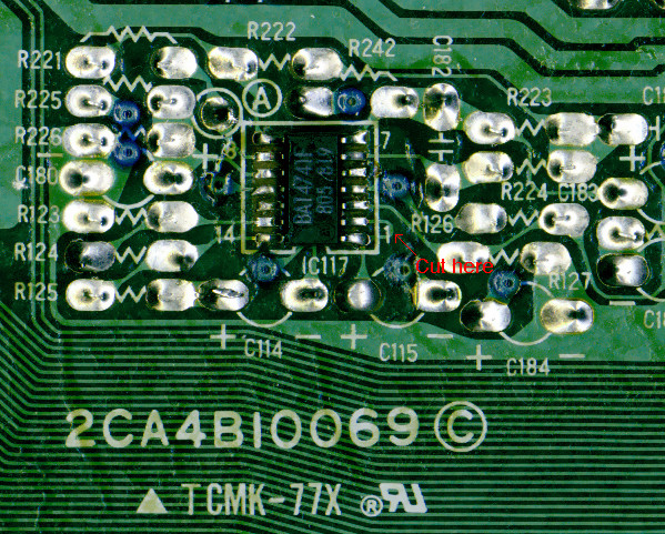
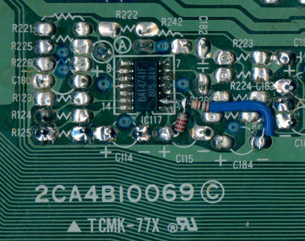
Then a small mod in the IC117 opamp is required to enhance the SNR
and the final audio output volume:
- Under the board, cut the track in "U" shape that connects the
pin-1 to the pin-2 of the IC117, right under the silkscreen has
a number "1"
- Solder a 1/8W 10K resistor to the IC117_pin2 and the C184
negative pin
- Solder a 1/8W 2K2 resistor to the IC117_pin2 and the C115
positive pin
The special thanks for this fix go to:
- Fábio Belavenuto, of FBlabs, for reverse engineering and
drawing the schematic of
the audio circuitry of this machine.
- The analog Jedi Master Sturaro, of MSXpro. Only by following his
valuable tips about what was wrong with the sound circuit I
could design this solution.
2.2) Panasonic MSX Turbo-Rs: FS-A1ST and FS-A1GT audio fix
The two Panasonic MSX Turbo-Rs have a very good audio circuit design
that has everything it should have for its price range. But the
result was poor because the circuit was terribly calibrated,
resulting amongst other problems, in:
- The slot sound was too loud, meaning you could barely hear
the PSG drumkit on when an SCC cartridge was used.
- OTOH, the OPLL sound was too quiet, so the soundtracks of
Micro Cabin games, Valis-2, Starship Rendezvous and others that
used the OPLL and FM simultaneously were severely affected. Most
accords were derailed, and Micro Cabin's trick of using the PSG
as a "3rd operator" for the OPLL didn't match anymore. The PSG
kept screaming loud all the time.
- The OPLL low-pass filter was even stronger than the already
exagerated filter in the Yamaha reference design, resulting in a
terribly muffled FM sound that made the previous problem even
worse.
- The global audio-out low-pass filter was also too strong, to
the point that the borders of the square wave output of the PSG
were totally round, degrading many beautiful accords of famous
Konami soundtracks for this chip. The PSG "drumkits" also
sounded dull and lifeless.
- The global audio-out level was too weak, resulting in poor SNR
and weak bass.
This fix recalibrates the audio circuit for maximum performance, and
what astonishing difference that it does. It then blows any other
MSX sound quality out of the water. It corrects all these problems,
and normalizes the mixing volume between the slots (usually SCC or
MSX-Audio), PSG and OPLL, to match the levels of the Panasonic MSX2+
and Sony MSX2+ machines. All filtering of the circuit is calibrated
with the same parameters used in the famous high-end Yamaha SFG-05
module.
Here's the recipe:
a) FS-A1ST
C48 = 1n8/50V polyphenylene sulfide or C0G
ceramic
C49 = 1n8/50V polyphenylene sulfide or C0G
ceramic
R24 = 22K
R23 = 15K
C57 = 180pF/50V polyphenylene sulfide or C0G
ceramic
C159 = 150pF/50V polyphenylene sulfide or C0G
ceramic
b) FS-A1GT
C17 = 1n8/50V polyphenylene sulfide or C0G
ceramic
C18 = 1n8/50V polyphenylene sulfide or C0G
ceramic
R50 = 22K
R47 = 15K
R55 = 47K
C51 = 180pF/50V polyphenylene sulfide or C0G
ceramic
C45 = 150pF/50V polyphenylene sulfide or C0G
ceramic
Notes:
- All resistors and capacitors above are SMD size 0805
- C0G Ceramic SMD capacitors are also sometimes also called
"NP0", "COG", "NPO"
The special thanks for this fix go to:
- Laurens Holst, for finding the SFG-05 schematics that helped
to improve adjustment of the circuit filters and the sugestion
for the Polyphenylene Sulfide capacitors
2.3) Panasonic FS-A1GT jailbar fix
This machine has a design mistake that causes a very noticeable
jailbar effect on its RGB output. Fortunately, it's very easy to
fix.
This fix gives you three advantages:
- Eliminates the jailbars on the RGB output
- The DIN9 RGB pinout becomes standard
- Clearer and sharper CVBS (aka composite-video) output
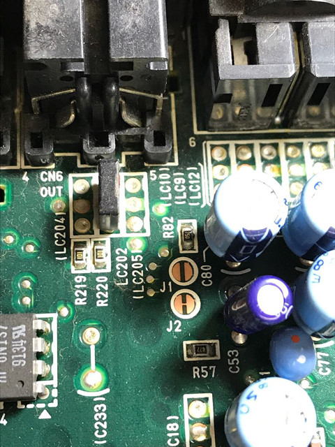
On the motherboard, there look for a pair of jumpers called J1 and
J2. Use the picture below as a reference:
These jumpers select whether CVBS or CSYNC will be sent to the DIN9
RGB output connector. By default CVBS is selected. But this signal
contains a high frequency color carrier that shows up in most
monitors as jailbars. Thankfully, the CSYNC signal is clean
and it's also a more adequate signal to be sent to the DIN9, as it
will match the pinout of the A1ST and all the MSX2+ models.
So, to fix the problem, just cut the J2 jumper open and solder a
drop of solder tin to close the J1 jumper.
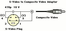
But this also means you won't have CVBS (aka composite video) from
the DIN9 connector anymore. This can be easily solved with a
different break-out cable. Until now, you had to use a DIN9 ->
CVBS breakout cable. From now on, you just have to use an S-Video
-> CVBS breakout cable. I wonder why the Panasonic engineers just
didn't use this solution from the beginning, instead of having
modified the DIN9 pinout and created incompatibilities.
Build the the S-Video to CVBS breakout cable like this:
The special thanks for this fix go to:
- Leonard Oliveira, for discovering and sharing the J1/J2 fix
2.4) Philips NMS-8250, NMS-8255 and NMS-8280
This sound circuit is just unbelievably broken by design. It's the
worst I have ever seen.
The circuit design seems to have been reused from an earlier cheap
MSX1 machine, but then the engineer moved the amplifier section to
the wrong place (only for the PSG line, that is usually louder than
the other sources), and ruined for once what already wasn't exactly
a great design.
IOW, the circuit only works properly for the internal PSG and you're
lucky if anything else connected to the slot produces any sound. And
I wouldn't recommend to connect two sound cartridges at the same
time to these machines, because it short-circuits their sound outputs.
The RetroMSX
page has a good fix created by Aquijacks, that copies the
circuit from the NMS-8245 and fixes the circuit of the
NMS-8250/8255/8280. The document is in Spanish, but Google Translate
can help you with that.